Introduction
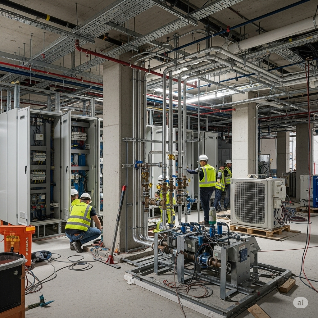
In the complex choreography of construction projects, Mechanical, Electrical, and Plumbing (MEP) services form the invisible backbone that brings buildings to life. This blog post focuses specifically on critical MEP components including power backup systems (DG, UPS), water sources, water treatment plants (WTP), reverse osmosis (RO) systems, sewage treatment plants (STP), organic waste converters (OWC), and waste management systems.
Whether you’re a seasoned professional, a fresh engineering graduate, a developer, or simply someone planning to build their first home, understanding these systems is essential for successful project execution and long-term operational efficiency.

Project Life Cycle Overview
Before diving into specific systems, let’s understand how MEP works fit into the overall project lifecycle:
- Conceptualization & Pre-design – Establishing requirements, feasibility studies
- Design Development – Creating detailed specifications and drawings
- Tendering & Procurement – Selecting vendors and acquiring equipment
- Installation & Construction – Physical implementation
- Testing & Commissioning – Verifying functionality and performance
- Handover & Operations – Training and transfer to end-users
- Maintenance & Upgrades – Ongoing support and improvements
Now, let’s explore each MEP component in detail.
Power Backup Systems
Diesel Generators (DG)
Key Methodologies for Execution
DG sets provide emergency power during outages and are critical for essential services like elevators, fire systems, and medical equipment.
- Load Analysis: Calculate essential and non-essential loads to determine required capacity
- Selection & Sizing: Choose appropriate DG capacity with N+1 redundancy for critical facilities
- Location Planning: Identify suitable location considering noise, vibration, ventilation, and fuel storage
- Installation: Follow manufacturer guidelines and electrical safety standards
- Integration: Connect with building management systems for automatic operation
Material and Manpower Requirements
| Material | Specification | Purpose |
|---|---|---|
| DG Set | IS 4722, BS 5514 | Primary equipment |
| Acoustic Enclosure | CPCB norms | Noise reduction |
| AMF Panel | IS 8623, IEC 60947 | Automatic operation |
| Cables | IS 1554, IS 7098 | Power distribution |
| Earthing System | IS 3043 | Electrical safety |
CPCB noise pollution guidelines
Manpower:
- Electrical Engineer (1)
- DG Installation Technicians (2-4)
- Helpers (2-3)
- Testing & Commissioning Engineer (1)
Deliverables at Different Stages
Design Stage:
- Load calculations
- Single line diagrams
- Location and space planning drawings
- Technical specifications
Installation Stage:
- Foundation and vibration isolation details
- Fuel system design
- Exhaust system layout
- Acoustic treatment design
Commissioning Stage:
- Load test reports
- Noise level certification
- Fuel consumption analysis
- Operations & maintenance manuals
Key Stakeholders and Communication
- Client/Owner: Final approval authority
- Project Manager: Overall coordination
- Electrical Consultant: Technical specifications
- DG Vendor/Supplier: Equipment and installation
- Electrical Contractor: Installation and integration
- Statutory Authorities: Pollution control board approvals
- Testing Agency: Third-party verification
Communication Matrix:
| Information | From | To | Format | Frequency |
|---|---|---|---|---|
| Load Requirements | Electrical Consultant | All | Technical Report | Design stage |
| DG Specifications | Supplier | Project Manager | Technical Submittal | Pre-procurement |
| Installation Progress | Contractor | Project Manager | Progress Report | Weekly |
| Test Results | Testing Agency | All | Test Report | Post-commissioning |
Design Basis Calculations
DG Sizing Formula:
DG Capacity (kVA) = (Total Connected Load × Diversity Factor × Load Factor) / Power FactorTypical Diversity Factors:
- Residential: 0.5-0.7
- Commercial: 0.7-0.8
- Industrial: 0.6-0.9
- Hospitals: 0.8-0.9
Fuel Tank Sizing:
Tank Volume (L) = DG Fuel Consumption (L/hr) × Required Runtime (hrs) × 1.2 (safety factor)
Value Engineering Opportunities
- Hybrid Systems: Combine DG with renewable energy sources (solar PV) to reduce operational costs
- Load Segregation: Separate critical and non-critical loads to optimize DG capacity
- Heat Recovery: Utilize waste heat for building heating or hot water systems
- Smart Controllers: Implement intelligent load management to optimize fuel consumption
- Modular Approach: Use multiple smaller DG sets instead of a single large unit for better redundancy and efficiency at partial loads
Uninterruptible Power Supply (UPS)
Key Methodologies for Execution
UPS systems provide instantaneous power protection against outages and fluctuations.
- Load Criticality Analysis: Identify sensitive equipment requiring uninterrupted power
- Runtime Calculation: Determine required backup time
- Topology Selection: Choose between online, line-interactive, or offline UPS
- Battery Selection: Calculate battery capacity and type
- Installation & Integration: Implement with proper ventilation and temperature control
Material and Manpower Requirements
| Material | Specification | Purpose |
|---|---|---|
| UPS Unit | IEC 62040 | Primary equipment |
| Batteries | IS 16270 | Energy storage |
| Mounting Racks | ASTM standards | Structural support |
| Distribution Panel | IS 8623 | Power distribution |
| Monitoring System | – | Performance tracking |
Manpower:
- Electrical Engineer (1)
- UPS Installation Technicians (2)
- Battery Technicians (2)
- Helpers (1-2)
Deliverables at Different Stages
Design Stage:
- Load calculations
- Battery sizing calculations
- Space planning drawings
- Single line diagrams
Installation Stage:
- Battery room layout
- Ventilation design
- Fire safety measures
- Grounding systems
Commissioning Stage:
- Load test reports
- Runtime verification
- System efficiency measurements
- Handover documentation
Key Stakeholders and Communication
- Client/End User: Requirements definition
- Electrical Consultant: System specification
- UPS Vendor: Equipment supply and commissioning
- Electrical Contractor: Installation and integration
- Facility Management: Ongoing operations
Design Basis Calculations
UPS Sizing Formula:
UPS Capacity (kVA) = (Total Critical Load × Crest Factor) / Power FactorBattery Sizing:
Battery Capacity (Ah) = (Load in Watts × Backup Time in Hours) / (Battery Voltage × End-of-Discharge Voltage × Efficiency)
Value Engineering Opportunities
- Modular Architecture: Implement scalable UPS modules for future expansion
- ECO Mode Operation: Use energy-efficient operating modes for non-critical applications
- Lithium-Ion Batteries: Consider alternative battery technologies for longer life and smaller footprint
- Distributed UPS Systems: Use multiple smaller units closer to loads instead of centralized systems
- Power Factor Correction: Implement correction devices to optimize UPS efficiency
Water Sources & Treatment Systems
Water Sources
Key Methodologies for Execution
- Water Demand Assessment: Calculate daily water requirements based on occupancy and usage
- Source Identification: Evaluate municipal supply, groundwater, rainwater harvesting potential
- Quality Analysis: Test source water quality parameters
- Storage Design: Size underground and overhead tanks
- Distribution Planning: Design pumping systems and distribution networks
Material and Manpower Requirements
| Material | Specification | Purpose |
|---|---|---|
| Storage Tanks | IS 12701 | Water storage |
| Pumps | IS 8034, IS 9079 | Water transfer |
| Piping Systems | IS 4985, IS 15778 | Distribution |
| Level Controllers | – | Automation |
| Water Meters | IS 779 | Consumption monitoring |
Manpower:
- Civil Engineer (1)
- Plumbing Engineer (1)
- Plumbers (3-4)
- Helpers (4-6)
- Electrician (1)
Deliverables at Different Stages
Design Stage:
- Water demand calculations
- Source assessment reports
- Storage tank sizing calculations
- Pumping system designs
Installation Stage:
- Underground tank construction drawings
- Pump room layout
- Distribution network plans
- Automation system schematics
Commissioning Stage:
- Water quality test reports
- Pressure testing reports
- Flow rate verification
- System balancing documentation
Key Stakeholders and Communication
- Client/Owner: Requirements and approvals
- MEP Consultant: System design
- Plumbing Contractor: Installation
- Municipal Authorities: Approvals and connections
- Water Testing Agency: Quality verification
Design Basis Calculations
Daily Water Demand:
Residential: 135-200 liters per person per day (as per IS 1172)
Commercial: 45-70 liters per person per day
Industrial: Project-specific calculations
Storage Capacity:
Domestic Storage = Daily Demand × Storage Factor (1-2 days based on reliability of source)
Fire Reserve = As per National Building Code (NBC)
Pump Sizing:
Pump Capacity (LPM) = Flow Rate Required
Pump Head (m) = Static Head + Friction Losses + Residual Pressure
Value Engineering Opportunities
- Dual Plumbing Systems: Separate potable and non-potable water networks
- Pressure Zoning: Create different pressure zones for multi-story buildings
- Variable Frequency Drives: Use VFDs on pumps to optimize energy consumption
- Smart Water Metering: Implement digital monitoring systems for early leak detection
- Rainwater Integration: Design systems to prioritize rainwater usage when available
Water Treatment Plant (WTP)
Key Methodologies for Execution
- Raw Water Analysis: Test source water quality parameters
- Treatment Process Selection: Choose appropriate technologies based on raw water quality
- System Sizing: Calculate treatment capacity based on daily demand
- Technology Selection: Evaluate filtration, disinfection, and softening requirements
- Layout Design: Optimize space utilization and maintenance access
Material and Manpower Requirements
| Material | Specification | Purpose |
|---|---|---|
| Multimedia Filters | IS 8419 | Particulate removal |
| Activated Carbon Filters | – | Odor and taste removal |
| Softeners | – | Hardness removal |
| Dosing Systems | – | Chemical treatment |
| Control Panels | IS 8623 | Automation |
Manpower:
- Process Engineer (1)
- Plumbing Engineer (1)
- Technicians (2-3)
- Helpers (2-3)
- Electrician (1)
Deliverables at Different Stages
Design Stage:
- Water quality analysis report
- Process flow diagrams
- P&ID drawings
- Equipment specifications
Installation Stage:
- Equipment layout drawings
- Piping schematics
- Control system designs
- Chemical dosing systems
Commissioning Stage:
- Treated water quality reports
- Performance test documentation
- Operating procedures
- Maintenance schedules
Key Stakeholders and Communication
- Client: Requirements and approvals
- MEP Consultant: System design
- WTP Specialist: Process design
- Contractor: Installation
- Health Authorities: Compliance verification
Design Basis Calculations
Filtration Rate:
Filter Area (m²) = Flow Rate (m³/hr) / Filtration Rate (m³/m²/hr)Backwash Requirements
Backwash Water Volume = Filter Area × Backwash Rate × Backwash DurationChemical Dosing:
Dosing Rate (L/hr) = Flow Rate (m³/hr) × Dosage (mg/L) / Solution Concentration (%)
Value Engineering Opportunities
- Membrane Filtration: Consider ultrafiltration for improved water quality
- Regeneration Optimization: Implement counter-current regeneration for softeners
- Automation: Add real-time monitoring and automatic backwashing based on pressure differential
- Chemical Optimization: Use online analyzers to optimize chemical dosing
- Heat Recovery: Recover heat from backwash water in hot water applications
Reverse Osmosis (RO) System
Key Methodologies for Execution
- Feed Water Analysis: Test all parameters affecting RO performance
- System Design: Calculate recovery rate, flux, and membrane configuration
- Pre-treatment Selection: Design appropriate pre-treatment to protect membranes
- Post-treatment Design: Plan remineralization if needed
- Reject Management: Design proper disposal or recovery of reject water
Material and Manpower Requirements
| Material | Specification | Purpose |
|---|---|---|
| RO Membranes | ANSI/NSF 61 | Filtration |
| High-Pressure Pumps | – | Pressure generation |
| Pre-treatment Systems | – | Membrane protection |
| Control Systems | – | Automation |
| Antiscalant Dosing | – | Membrane protection |
Manpower:
- RO Specialist (1)
- Plumbing Engineer (1)
- Technicians (2)
- Helpers (2)
- Electrician (1)
Deliverables at Different Stages
Design Stage:
- Water quality analysis
- System sizing calculations
- Process flow diagrams
- P&ID drawings
Installation Stage:
- Equipment layout
- Piping diagrams
- Electrical schematics
- Instrumentation details
Commissioning Stage:
- Performance test reports
- Recovery rate verification
- Product water quality testing
- Operational manuals
Key Stakeholders and Communication
- Client: Requirements and approvals
- RO System Supplier: Equipment and design
- MEP Consultant: Integration with building systems
- Contractor: Installation
- Water Quality Specialist: Testing and verification
Design Basis Calculations
System Capacity:
RO Capacity = Daily Permeate Requirement / (24 hrs × Utilization Factor)Recovery Rate:
Recovery (%) = (Permeate Flow / Feed Flow) × 100Membrane Area:
Membrane Area (m²) = Permeate Flow (m³/day) / Flux (m³/m²/day)
Value Engineering Opportunities
- Energy Recovery Devices: Implement pressure exchangers for high-capacity systems
- Two-Pass Design: Use two-pass RO for critical applications only
- Concentrate Recovery: Design systems to reuse concentrate water for appropriate applications
- Smart Monitoring: Implement real-time monitoring to optimize cleaning frequencies
- Hybrid Systems: Combine RO with other technologies like ultrafiltration for optimized performance
Waste Management Systems
Sewage Treatment Plant (STP)
Key Methodologies for Execution
- Sewage Flow Estimation: Calculate daily sewage generation
- Technology Selection: Choose between ASP, MBBR, SBR, MBR based on requirements
- Hydraulic Design: Size chambers, tanks, and pipes
- Mechanical Design: Select pumps, blowers, and diffusers
- Electrical & Automation Design: Plan control systems and instrumentation
Material and Manpower Requirements
| Material | Specification | Purpose |
|---|---|---|
| Concrete Tanks | IS 456 | Treatment chambers |
| Aeration System | – | Biological treatment |
| Pumps | IS 8034 | Transfer and recirculation |
| Filter Press | – | Sludge dewatering |
| Control Panel | IS 8623 | Automation |
Manpower:
- Environmental Engineer (1)
- Civil Engineer (1)
- Mechanical Engineer (1)
- Technicians (3-4)
- Helpers (4-6)
- Electrician (1)
Deliverables at Different Stages
Design Stage:
- Sewage flow calculations
- Process design
- Hydraulic profile
- P&ID drawings
Installation Stage:
- Civil construction drawings
- Equipment installation details
- Piping layouts
- Electrical schematics
Commissioning Stage:
- Treated effluent quality reports
- Performance test documentation
- Operating procedures
- Maintenance schedules
Key Stakeholders and Communication
- Client: Requirements and approvals
- Environmental Consultant: Process design
- Pollution Control Board: Approvals and compliance
- Contractor: Installation
- Facility Management: Operations and maintenance
Design Basis Calculations
Sewage Flow:
Sewage Flow = 80% of Water SupplyOrganic Load:
BOD Load (kg/day) = Population × Per Capita BOD (0.05-0.08 kg/person/day)Aeration Requirement:
Oxygen Requirement (kg/day) = BOD removed (kg/day) × 1.5
Value Engineering Opportunities
- Tertiary Treatment: Add polishing filters for landscape irrigation reuse
- Decentralization: Consider multiple smaller plants for large campuses
- SCADA Integration: Implement remote monitoring and control
- Solar Integration: Power STP operations with solar energy
- Heat Recovery: Recover heat from sewage for building heating
Organic Waste Converter (OWC)
Key Methodologies for Execution
- Waste Quantification: Estimate daily organic waste generation
- Technology Selection: Choose appropriate conversion technology
- Space Planning: Identify suitable location with proper ventilation
- Odor Management: Design systems to prevent odor nuisance
- Compost Utilization: Plan for compost storage and utilization
Material and Manpower Requirements
| Material | Specification | Purpose |
|---|---|---|
| OWC Machine | – | Waste processing |
| Shredder | – | Size reduction |
| Curing System | – | Compost maturation |
| Screening System | – | Compost refining |
| Odor Control System | – | Environmental protection |
Manpower:
- Environmental Engineer (1)
- Operator (1-2)
- Helpers (2-3)
- Maintenance Technician (1)
Deliverables at Different Stages
Design Stage:
- Waste generation analysis
- System sizing calculations
- Layout drawings
- Operating specifications
Installation Stage:
- Foundation drawings
- Machine installation details
- Utility connections
- Ventilation systems
Commissioning Stage:
- Performance verification
- Compost quality analysis
- Operations manual
- Training documentation
Key Stakeholders and Communication
- Client: Requirements and approvals
- OWC Supplier: Equipment and commissioning
- Facility Management: Operation and maintenance
- Landscape Team: Compost utilization
- Municipal Authority: Compliance verification
Design Basis Calculations
Waste Generation:
Residential: 0.1-0.15 kg/person/day
Commercial: 0.05-0.1 kg/person/day (excluding food establishments)
Food Establishments: 0.25-0.4 kg/meal served
Machine Sizing:
OWC Capacity (kg/day) = Daily Waste Generation × Peak Factor (1.2-1.5)Space Requirement:
Area (m²) = Machine Footprint × 3 (for operations and storage)
Value Engineering Opportunities
- Biogas Integration: Consider biogas generation for energy recovery
- Automated Feed Systems: Implement conveyor systems for larger quantities
- Compost Bagging: Add value by creating packaged compost products
- Heat Recovery: Utilize heat generated during composting process
- Leachate Collection: Design systems to collect and reuse nutrient-rich leachate
Solid Waste Management Systems
Key Methodologies for Execution
- Waste Characterization: Analyze waste types and quantities
- Collection System Design: Plan bins, chutes, and collection points
- Segregation Strategy: Design for at-source segregation
- Transportation Planning: Define movement paths and methods
- Disposal/Recycling Arrangements: Plan final disposal or recycling systems
Material and Manpower Requirements
| Material | Specification | Purpose |
|---|---|---|
| Collection Bins | IS 12402 | Waste collection |
| Garbage Chutes | – | Vertical transport |
| Compactors | – | Volume reduction |
| Transfer Carts | – | Horizontal transport |
| Weighing Systems | – | Quantity tracking |
Manpower:
- Waste Management Specialist (1)
- Collection Staff (varies with project size)
- Supervisor (1)
- Maintenance Staff (1-2)
Deliverables at Different Stages
Design Stage:
- Waste quantification report
- Collection system design
- Bin sizing and location plan
- Material flow diagrams
Installation Stage:
- Bin and equipment placement plans
- Chute system details
- Collection point construction
- Signage and instruction details
Commissioning Stage:
- Operational procedures
- Training materials
- Monitoring protocols
- Reporting templates
Key Stakeholders and Communication
- Client/Facility Management: Requirements and operations
- Waste Management Consultant: System design
- Municipal Authority: Compliance and collection
- Recycling Partners: Material recovery
- Residents/Occupants: User education and compliance
Design Basis Calculations
Waste Generation:
Residential: 0.3-0.6 kg/person/day
Commercial: 0.1-0.2 kg/person/day
Collection Frequency:
Frequency = Waste Generation / (Container Capacity × Fill Factor)Bin Sizing:
Bin Volume = Daily Waste × Days Between Collections × (1 + Peaking Factor)
Value Engineering Opportunities
- Pneumatic Waste Collection: Consider automated vacuum systems for large developments
- RFID Tracking: Implement tracking systems for bins and collection
- Pay-as-you-throw: Design systems to encourage waste reduction
- IoT Integration: Add fill-level sensors and route optimization
- Community Recycling Centers: Develop shared facilities for enhanced segregation
Case Study: Integrated MEP Systems in a Residential Township
Project Overview
Project Name: Green Valley Township
Location: Pune, Maharashtra
Scale: 500 apartments across 5 towers (G+14)
Special Features: IGBC Gold Rating targeted
Challenges
- Unreliable municipal water supply
- Frequent power outages (2-3 hours daily)
- Limited space for waste management facilities
- Strict environmental compliance requirements
Solution Implementation
Power Backup Integration
- DG System: 3 × 500 kVA DG sets with N+1 redundancy
- Load Segregation: Essential services (100% backup), non-essential services (partial backup)
- UPS System: Centralized 50 kVA UPS for common areas and 5 kVA UPS for each lift
- Solar Integration: 200 kWp rooftop solar PV connected to DGs for fuel saving during daytime outages
Water Management Solution
Source Diversification:
- Municipal supply (primary)
- Borewells (secondary)
- Rainwater harvesting (supplementary)
Treatment Train:
- Centralized WTP (500 KLD) for borewell water
- Building-level RO plants (20 KLD each) for drinking water
- STP (400 KLD) with MBR technology for wastewater recycling
Reuse Strategy:
- STP treated water for landscaping and toilet flushing
- Dual plumbing system for treated water distribution
Waste Management Implementation
Segregation System:
- Three-bin system at apartment level (wet, dry, hazardous)
- Separate collection chutes for wet and dry waste
Processing Systems:
- 500 kg/day OWC for wet waste conversion to compost
- Compaction and baling system for dry recyclables
- Tie-up with recyclers for material recovery
Results
Resource Conservation:
- 40% reduction in municipal water consumption
- 30% reduction in DG fuel consumption
- 95% waste diversion from landfill
Economic Benefits:
- ₹15 lakhs annual savings in water procurement costs
- ₹20 lakhs annual savings in electricity bills
- ₹5 lakhs annual revenue from compost and recyclables
Environmental Impact:
- 80% reduction in carbon footprint
- Zero discharge facility status achieved
- Enhanced green space quality through compost utilization
User Experience:
- Uninterrupted power supply for essential services
- Consistent water quality across apartments
- Odor-free waste management system
Essential Checklists for MEP Services
DG Set Installation Checklist
- Foundation designed as per manufacturer recommendations
- Vibration isolation pads/springs installed
- Acoustic enclosure meeting CPCB norms provided
- Exhaust piping with proper insulation installed
- Fuel tank with required capacity constructed
- AMF panel with required protection devices installed
- Earthing system as per IS 3043 completed
- Battery and charger system installed
- Control cables properly terminated and labeled
- Power cables sized correctly and installed with proper supports
- Ventilation system with required air changes provided
- Fire detection and suppression system installed
- NOC from Pollution Control Board obtained
- Load test at different load conditions conducted
- Noise level measurement conducted
- Training to operation staff provided
Water Treatment System Checklist
- Raw water quality analysis conducted
- Treatment process validated through jar tests
- Equipment sized based on peak demand calculations
- Redundancy provided for critical components
- Chemical dosing systems with containment installed
- Backwash system with proper disposal designed
- Instrumentation for quality monitoring installed
- Control panel with automation features provided
- Bypass arrangements for maintenance included
- Post-treatment stabilization system designed
- Treated water storage with proper capacity provided
- Chemical storage area with safety features designed
- Operator training conducted and documented
- Operation and maintenance manual provided
- Treated water quality testing conducted
- System performance verified against design parameters
STP Commissioning Checklist
- All civil structures checked for leaks
- Mechanical equipment alignment verified
- Electrical connections and earthing checked
- Control panel programming completed
- Instrument calibration verified
- Air blowers balanced and vibration levels checked
- Diffuser system uniformity verified
- Pumps primed and rotation direction checked
- Chemical dosing systems calibrated
- Hydraulic flow test conducted
- Process seeding completed
- MLSS buildup monitored and documented
- Treated effluent quality tested by approved laboratory
- Noise and odor levels verified
- Energy consumption measured and documented
- Staff training completed and competency verified
Additional MEP Services in Construction Projects
Beyond the systems discussed above, several other critical MEP services should be considered in comprehensive project planning:
HVAC Systems
- Centralized air conditioning systems
- VRF/VRV systems
- Chilled water systems
- Heating systems
- Energy recovery ventilators
- Building management systems for HVAC control
Building Management Systems (BMS)
- Integrated monitoring and control
- Energy management
- Indoor air quality monitoring
- Occupancy-based system optimization
- Remote monitoring capabilities
- Preventive maintenance scheduling
Renewable Energy Systems
- Solar photovoltaic systems
- Solar thermal systems
- Wind energy integration
- Geothermal heating/cooling
- Energy storage solutions
Security and Access Control Systems
- CCTV surveillance
- Access control systems
- Intrusion detection
- Video analytics
- Visitor management systems
- Security integration with BMS
Communication Systems
- Structured cabling
- Telephone systems
- Intercom systems
- LAN/WAN infrastructure
- Wireless networks
- Distributed antenna systems
Conclusion
The successful implementation of MEP services in construction projects requires careful planning, proper sizing, quality installation, and thorough commissioning. By following standard methodologies and adhering to relevant codes and standards, project teams can ensure reliable and efficient operations of these critical building systems.
For developers, engineers, and homeowners alike, understanding the lifecycle of these systems from conception to operation provides valuable insights for decision-making. The integration of value engineering principles further enhances the performance while optimizing costs.
As construction practices continue to evolve toward greater sustainability, the role of efficient MEP systems becomes increasingly important. By implementing best practices in power backup, water management, and waste handling systems, projects can achieve significant resource conservation while providing enhanced comfort and convenience to occupants.
References
- National Building Code of India 2016
- IS 1172: Code of Basic Requirements for Water Supply, Drainage and Sanitation
- CPWD Specifications for Electrical Works
- ISHRAE Handbooks for HVAC Design
- IS 3043: Code of Practice for Earthing
- Central Pollution Control Board Guidelines for DG Sets
- IS 8034: Specifications for Submersible Pumpsets
- Environmental Protection Rules, 1986 (for STPs)
- IS 2062: Steel for General Structural Purposes
- Energy Conservation Building Code (ECBC)
This blog post is intended as a general guide. Project-specific requirements may vary based on location, scale, and regulatory environment. Always consult qualified professionals for project implementation.


